Custom MV Agusta 500 Race Bike Replica
Select a link below to read about that part of the build with pictures to accompany the text, or simply scroll down to read about it from start to finish.
|
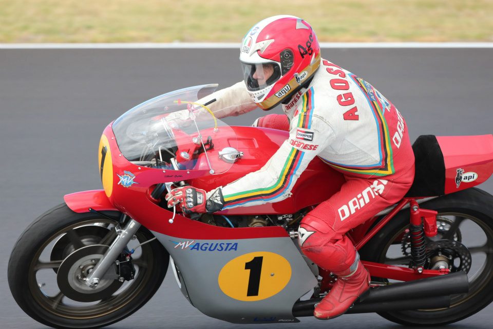
At the Phillip Island GP in Australia, January, 2013, Giacomo Agostini did some "parade" laps revving the bike to 11,500rpm and it was still pulling.
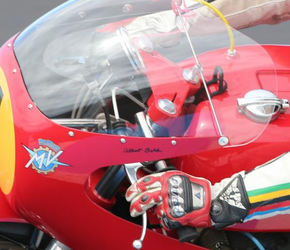
Left: Note Albert's signature on the fairing - a request from the owner. |
Pre-Build
Bike Pre-build
|
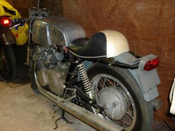
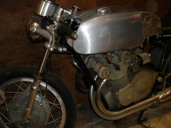
It started as a 1968 MV 600 racer.
|
At some point, a previous owner converted it to a cafe racer.
Water damage to the pistons caused them to seize.
|
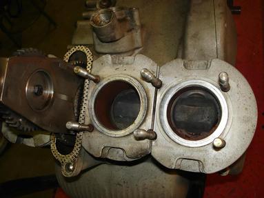
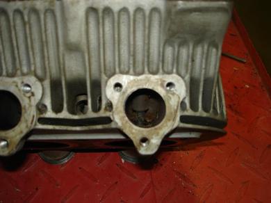
Intake ports where water got into the cylinder.
|
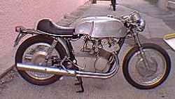
I first got to know Julian when he purchased an MV America back in 2009, which I had previously owned. We started to exchange e-mails concerning parts and information about the various MV’s he had. In 2010 Julian approached me about a special build: a 4-cylinder road racer based on a photograph of a 1975, 500 racer. The goal was to create a racer utilizing the “MV masters”: a Magni race frame, and Primo Fellotti body panels, tank, seat and faring. To my surprise, Julian requested I supply and build the motor for the bike. At that time I didn’t have any donors that were available for the project. About two months later I got a call from someone that had purchased a 600 MV along with a bunch of other motorbikes. He wanted me to bring it back to original configuration, but it needed so much work it really wasn’t worth the effort. I wound up buying the bike and offering the motor to Julian for the project. Once I received the bike I found out how bad it was. The pistons were seized but the motor was in pretty decent shape. Water had gotten into the intake ports, but not into the motor itself.
Motor Cases- Part 2
I first took it down to the cases and started there. I cut all the excess aluminum out of the castings and cleaned them up. I did some modifications to the exterior to lighten and clean up the lines. This included cutting off extra tabs and flashing on the motor. My first hurdle was to adapt a dry clutch to a motor that does not normally carry one. I wound up putting the cases up on the mill and started to plot my bearing locations. I was able to visualize exactly how it was going to look and was therefore able to forgo making all the complicated prints. Once I located the bearings I could see how thick I need to make the new clutch cover. I started with a 4 lb. piece of aluminum billet. I began cutting on the bandsaw and roughed in the outer contours going to a line that I scribed using the original cover. I transferred the original screw locations to the rough blank so I could mount the billet piece to the sump. This allowed me to put in locator holes where the output shaft would run. After the hole was put in, I used that for a reference and the cutting was now underway. I turned the housing on the lathe and cut in the entire back side of the billet to receive the clutch gear and large seal. After that I cut in pockets for clearance and space needed for matching the casting. More time was spent lightening the cover on the rotary table, after which I assembled the cover and hand -filed the parts for a perfect match to the sump.
Crank Rebuild- Part 3
The next step was to get the crank together and set it into the motor for matching to the clutch gear. I pulled the carrier apart and found the crank was in great shape. Unfortunately, I was not able to use the stock 600 cra...nk because it had straight cut gears and didn’t fit the dry clutch helical gear. However, this wasn’t a problem, I had a newer crank in my spare parts. I disassembled the crank shaft and replaced the stock connecting rods with superior Carrillo racing rods which were custom made to my specifications. The modification went along perfectly and the rods looked great! I installed the crank and took some measurements for the correct backlash with the clutch gear. I wound up making a new locator pin for the upper case with offset to achieve the correct lash. Once it was assembled I had to trim the outer castings to hide the new location of the crank carrier since it had moved the upper casting back about .035. This meant it wasn’t matched externally. After the crank was done I bored out the upper part of the carrier to receive the new cylinders. I made the cylinders out of two pieces of 7075 aluminum and are currently 71mm, which allows an overbore of a maximum of 72mm. I chose to combine the two left and two right cylinders into one solid left and one solid right piece, similar to the way Arturo Magni designed his cylinders. The cast iron sleeves were from a KZ-1000 Kawasaki machined and fit with exactly .003 interference to the cylinder walls. Flanges were grooved for copper wire for a better seal against the head gasket. Pistons were custom made for me by Arias. I went further by specially lightening them for balance and strength by internally machining them.
The Head- Part 4
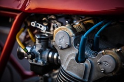
The head started out with 29mm intake and exhaust valves. Initially it had a small combustion chamber designed for a 58mm piston. The dome was way too small for a 71mm piston, so I had to increase the volume and enlarged the capacity comparable to a 750 America. I used a trick with a flycutter to generate a perfect sphere and get an exact depth and diameter which was much more accurate than the original factory design. I utilized a special fixture I designed to hold the head to get the chambers within .001 in depth and diameter. Since the casting was so small, I had to weld up the deck of the head to enlarge the surface for the cylinders to seal correctly. This also allowed me to install larger valves. I installed newer, larger seats made from aluminum bronze, which has served me well in the past with turbo and nitro heads I have built for the drag racing industry. Once I put in the seats, I enlarged the ports to 28mm and was able to raise the intake side by approx 3mm (.118”). I designed a new set of intake manifolds specifically for raising the ports and adapting a new set of PHBH-28 Dellorto carburetors. Doing this matched and equalized the ports for the maximum flow. Once I had the ports located and roughed in, Mike Hubsher from Lazer Porting, finished up the bowls and matching of the new angles by hand. The new carbs I made were ganged together with two manifolds made of aluminum, which stabilized the assembly. I made up some custom titanium bell mouths for better air intake, the actuator arms were fitted, and return springs ground for smooth throttle response. In addition, I modified the rear body of the carburetor by machining it smooth for better flow. The weight of my assembly is 2,618 grams versus the aftermarket units at 4,276 grams.
Internal Parts- Part 5
I cut down and modified the timing case for the gear tower that drives the cams. I machined out the outer iron housing to lighten the casting and fitted the gear bosses with 7075 aluminum plugs that supported the gear assembly and used titanium bolts and special nuts. Gears were also lightened to cut down on rotational weight which is crucial to quick acceleration and throttle response. Cams and cam gears were also modified for lightness by drilling and filleting. The cam profiles have extra lift and duration compared to stock. The intake cam I received from The Kays in Great Britain, and the exhaust cam was a stock cam taken from an America motor. Stock valve buckets were discarded and newer lighter ones I had in stock were installed. I made the valve guides from aluminum bronze and made an elliptical profile for improved flow characteristics. 29.5mm stainless steel valves were used on the exhaust and 33mm titanium valves on the intake. Both valves were reduced from a 7mm stock to 5.5mm stem. All valves were held in with my own retainers and the springs were high performance units from a GS-1100 Suzuki. Seat pressure of the valve was around 55lb. when closed. My combination seems to safely spin the motor to 11,500 RPM which is way up from the stock 8,500 RPM redline. All of the internal shafting and drive train were modified and lightened. All the drive gears behind the clutch basket were cut down and lightened. The jackshaft for the oil pump was made from titanium specially fit and hollowed out for this motor. The horizontal magneto shaft was also made hollow to be extra light.
Racing Magneto- Part 6
I took a Keikhaeffer racing magneto from a Mercury 4-cylinder outboard motor and reconfigured the internal breaker system. These magnetos rotate counter clockwise. The MV rotates clockwise and the magneto won’t work well spinning backwards, so I had to redesign the breaker plate and rotor. I found the correct phase of the magnets and had to make up a new plate that put the points in the correct orientation for optimum voltage output. With this change I now had a great spark that doesn’t miss at all. Years ago I thought I had the problem solved when I reworked one by indexing the rotor one tooth. It worked OK, but when I tested my old reliable magneto on Julian’s bike it was missing spark intermittently and for no apparent reason. After two days of testing and doing some spark analysis I found the breaker plate was out of phase. Once I got the new plate designed it threw one hell of spark and didn’t miss anymore. Problem solved! The magneto has a titanium driveshaft and was attached via an adjustable coupling to get the timing perfect. The magneto snout has degree increments cut into the outer flange, so timing can be adjusted visually and accurately to 1/2 degree of rotation.
Exhaust Pipes- Part 7
Julian chose to go with the straight pipes not the classic GP or curved pipes. The megaphones were made from sheet steel and were rolled and welded to a certain length that matched that of the 500 racer we were copying. I have my own style taper that I use when I make up the cones. I also weld in my own baffle that gives the pipe a better sound. I came up with the design about 10 years ago when I was trying to get the best sound out of an open pipe. Additionally, it is pretty light. Headers are made out of 4130 chromoly thin wall tube to save weight. The weight is a little more than half that of the stock system and is slightly smaller dimensionally.
Frame- Part 8
Originated from Magni. I purchased the frame in 2009 and had it in the shop for a couple of years for another job that fell through. I needed to fit the sump and do some frame modifications. I removed all tabs and unnecessary brackets and needed to add some since the shifter is on the wrong side. I stripped the frame of all the heavy paint to get started. Once it was stripped I found that all the welding was very poorly done. In certain areas the welds ran off of the fillet. There were sections where the welded area was very rough, had lumps, and holes. I wound up re-welding some areas and doing a lot of work cleaning up places that were clearly not acceptable for the look I was trying to achieve. After the cutting, cleaning, filing and grinding, I still had to clean and fix every weld joint and connection on the frame. I used body filler to get a smooth look in all areas that needed attention. It required 50 hours of additional hand work, sanding and filing, to make the frame look as nice as it did. Some of the tubes in the steering head were out of place and caused me to be concerned with the accuracy of the geometry. I was clearly disappointed in the quality control of the frame. Buried under a thick coat of red paint, the bad welds and holes were not apparent to the eye until you got very close. It took stripping the paint to make this more visible.
Sump & Chain Drive- Part 9
When I finally got the frame done, I put in the sump with the chain drive attached to see how the swing arm would look and made sure I had the right drive line for the front sprocket to rear wheel. The swing arm was pretty decent and needed minimal attention to make it look good. I did elect to get rid of the steel axle and heavy eccentric axle adjusters and replaced them with my own made of titanium and 7075 aluminum. Some EPM aluminum mag wheels were fitted and modified to accept the thinned down sprocket and 520 chain. The correct driveline was achieved by cutting down the hub and moving in the sprocket carrier and cush drive. For the rear brake, I took a Subaru disc brake and cut it down and fit it to a stock aluminum carrier that came off an MV America. The brake caliper was hung using a magnesium bracket which was attached to the motor so it would have a torque reaction when activated. All steel bearing spacers and bolts were replaced with titanium. The new axle and eccentrics also helped center the wheel. The axle was gun drilled for lightness. The swing arm pivot and shifter shaft were also made from titanium and gun drilled. Marzocchi Strada rear shocks are used for the rear suspension and were attached with custom titanium hardware made in house. In order to keep it true to the period we decided to go with the vintage Ceriani forks, of which I had only one left slider in stock. For about 30 years I had been looking for a mate to complete the set and had not found one. Coincidentally, at that time I was contacted by an acquaintance that was selling a bunch of MV parts. Just by chance he happened to have one right fork slider! Next, I got some new Ceriani fork tubes in Canada and wound up cutting them shorter to match the original length used on the America. My next problem was to find the internal baffling, which no longer exists. I did have a sample fork to go by. I was restoring an America, so when I got to the forks, I took them completely apart and made up all the valving and shafts from titanium and special alloys for the rebound pistons. I couldn’t find the extra light springs for the valve baffle and had to make them using titanium weld wire. The parts worked as well as the stock units when I tested them. The triple clamps were stock MV parts and the steer tube was made from 7075 aluminum. The front EPM wheel was a match to the rear and I had to modify it to take the plasma coated aluminum disks. Once the wheels were on I had to finish up the engine.
Body Components- Part 10
The next part of the operation was to make up the running gear and attach the seat, tank, and fairing. I couldn’t get the correct period clip-ons, so I made them. Out of…you guessed it: titanium. Super light and strong, they looked great in contrast to the red frame and other polished parts. The fairing brackets were also titanium and the mounting plates were magnesium. Brake and clutch cables went on and the angle of the clip-ons cleared the hand cutouts of the fairing with room to spare. I was ready for the seat and tank. Eight to ten months earlier, when we had first started the project, Julian had suggested we cut the frame and move the seat forward to minimize the seat area. At that time I suggested we have Giovanni make a 2 inch longer tank since the tank still needed to be made. Julian followed through right away and talked to Magni in April 2011 to place the order for the special tank. From that time on we anticipated the arrival of the new tank. We continued to wait and were now entering the end of January of 2012. Finally, January 12th the new tank arrived and as I unpacked it I noticed it was the wrong style tank. In addition, it was uneven and very poorly made. It was the worst thing I had ever seen. I sent pictures to Giovanni and he immediately took care of the problem. I am still not sure what went on with his tank maker but the next one was perfectly symmetrical and the correct style. Giovanni did ask me to pressure test it, because neither he nor the tank maker had had a chance to do that. I found 5 leaks, not uncommon for a hand built tank, but now I had more work to do. It seemed like I was hitting every speed bump imaginable. At this time I had been hoping I would have clear sailing from here on in. I got the tank welded up and was able to close all the leaks. I prepared the tank for primer and body filler and after 7 hours of filing and sanding, more filling and sanding it was finally done and ready for paint. The 7 hours were spread over a two week period so the primer and filler can cure and shrink completely so there are no waves and shadows later. Paint and decals came next, then off to my good Friend Tony Giovanetti for the clear coat. If it wasn’t for Tony the bike wouldn’t look as good as it does. Now the bike was finally taking shape in the standard fire-engine red.
Motor & Transmission- Part 11
The motor went together fairly well, but I had to take extra care in assembling the parts. I shimmed the correct clearances for the valves using my special tool steel shims. I dry fit one of the pistons without the cylinder so I could see how much clearance I had valve to valve and piston to valve and at top dead center (TDC). It took me a while to get the cams timed properly since there was not a lot of room for indicators around the valve bucket area, so I had to make a special indicator in order to read the correct lift of the cams. After that I bolted it together. The top end was now finished.
My second year of racing I had decided to use the 600 trans in the WERA GNF since it didn’t have as long a straightaway as some of the other tracks. On lap 3 the transmission started going away by not shifting properly and hitting false neutrals going into most of the turns. I found out later the gear teeth were folding over and this was preventing the gears from sliding smoothly on the shafts. Having this problem caused me to get much closer to the ground and I developed the V shaped vein that still runs up between my eyes, particularly when I am concentrating! I won the race and was thankful I didn’t crash. From that point on I chose to run the closer ratio transmission of the America. The 600’s gearing has a better ratio for street use and was a perfect donor for the long legged 750 America transmission Julian had. The transmission from the donor bike was in perfect shape, so I suggested we switch that transmission with his America’s. Julian agreed and sent me the transmission from his bike. I had to do some trimming of the shifter forks and then the transmission went right in. After that I started to make up the shifter linkage and rearsets. All titanium levers and shafts - rifle drilled for lightness. When I finally got the linkage done, I found that the shifter was not smooth and stuck from second into third, but nowhere else. I had the door off and transmission out about 8 times before I saw that the shifter shaft paw retainer was about .003 too thick. There was no easy way to measure the area where the shaft was sitting, but I had to eliminate all the other variables before I was able to figure out that this was the problem. Now I finally had the motor components done. Assembly was a real problem with the dry clutch. The intermediate gears that ran behind the clutch gear had to be put in after the clutch gear was installed. This required fishing parts through the lightning holes in the face of the clutch gear. After a lot of swearing, this section was finally together.
My second year of racing I had decided to use the 600 trans in the WERA GNF since it didn’t have as long a straightaway as some of the other tracks. On lap 3 the transmission started going away by not shifting properly and hitting false neutrals going into most of the turns. I found out later the gear teeth were folding over and this was preventing the gears from sliding smoothly on the shafts. Having this problem caused me to get much closer to the ground and I developed the V shaped vein that still runs up between my eyes, particularly when I am concentrating! I won the race and was thankful I didn’t crash. From that point on I chose to run the closer ratio transmission of the America. The 600’s gearing has a better ratio for street use and was a perfect donor for the long legged 750 America transmission Julian had. The transmission from the donor bike was in perfect shape, so I suggested we switch that transmission with his America’s. Julian agreed and sent me the transmission from his bike. I had to do some trimming of the shifter forks and then the transmission went right in. After that I started to make up the shifter linkage and rearsets. All titanium levers and shafts - rifle drilled for lightness. When I finally got the linkage done, I found that the shifter was not smooth and stuck from second into third, but nowhere else. I had the door off and transmission out about 8 times before I saw that the shifter shaft paw retainer was about .003 too thick. There was no easy way to measure the area where the shaft was sitting, but I had to eliminate all the other variables before I was able to figure out that this was the problem. Now I finally had the motor components done. Assembly was a real problem with the dry clutch. The intermediate gears that ran behind the clutch gear had to be put in after the clutch gear was installed. This required fishing parts through the lightning holes in the face of the clutch gear. After a lot of swearing, this section was finally together.